5. Crystal Centering and Data Collection
Under active development is a new CONSOLE script, which permits most of the user's operations within a single window (on "auxialliary" computer) using tabular format. Currently users should NOT use ADCS computer ( except for data visualization ) and MD2 computer;
The user should paid a lot of attention to updated features and detailed instruction given by your support personnel.
Now on the AUXILIARY computer, when you are starting PHI_MD2_FULL_REDIS.CXL script (how to start the script see this), you will see different tabs:LIFT, ROBOT, XTAL CENTERING, DATA COLLECTION, DETECTOR CONF, AP/BS ALIGN, and some others (for beamline personnel use only)
Two tabs: XTAL CENTERING and DATA COLLECTION tabs are regularly used during most of user operations.
XTAL CENTERING is the extension of the centering mode of MD2 software for use with mini-kappa goniometer and several robot manipulation tasks.

Figure 6. General view of "XTAL CENTERING" tab
There are several embedded operations in this window (from left
top corner clockwise):
1. Robot puck ID number (current) and the
button to mount next crystal - "CHANGE"; when "BUSY'
light is on - the robot is busy doing something, wait before
clicking. You can also dismount a currently mounted crystal or wash
it.
2. Section to control camera zoom, lighting of the crystal, and ability to acquire or view your crystal picture. StartServer button should be used only if the separate visual window is not started automatically (to be used by beamline personnel only).
3. The function
to acquire STAC strategy parameters from RAPD for better crystal
alignment (i.e long axis close to omega rotation axis) and align the
center of the crystal at new kappa/phi. Make sure you are using the
correct values and the most recent ones (check timestamp). “Align” will
automatically re-center the crystal to the new kappa/phi orientation in
small steps.
4. Controls to manually adjust Kappa/Phi/Omega for mini-kappa; if using single-axis goniometer-only omega should be used; predefined crystal rotations to check the alignment. Users are advised not to change kappa angle more than 40 degrees in one step, as the crystal may go out of the cold stream.
5. Three button to change MD2 mode: Center(default), Data collection and Sample Transfer
6. Buttons for crystals rotation and input field for a specific phi(omega)-angle, including vial mount.
7. 3-CLICK alignment tools, including alignment for crystal rastering: First, CLEAR the database, second do 3-CLICK at the beginning of the raster vector, press RECORD; third, repeat 3-CLICK centering at the end of the rastering vector, and press again RECORD, it should be number 2 in the left box. DISPLAY will show consequently the beginning and the end of the raster vector and REPLAY will repeat two alignment processes. More than two points may be created for complex cases. 3-click alignment should be completely finished, before proceeding to the next operation. ABORT should be used to leave the "3-click" function.
8. Snapshot button to collect snapshots – a snap constructor dialog will appear - (no need to go to different tab)
9. Buttons for manual movements of the crystal: vertical, horizontal and along the beam (out-focus plane). 1, 10 or 50 microns increments.
DATA COLLECTION tab is used to control ADSC snapshot/data collection parameters.
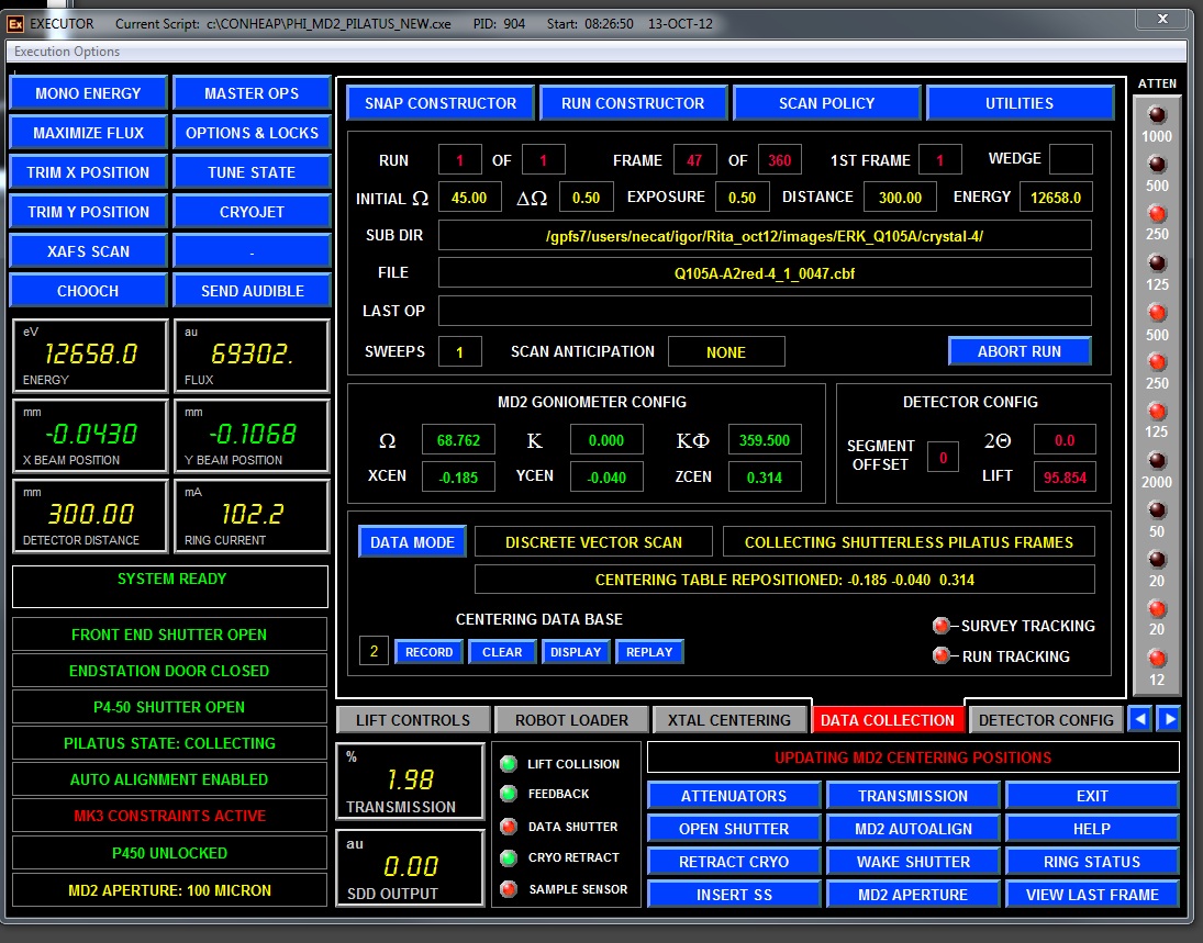
Figure 7. General view of "DATA COLLECTION" tab
SNAP CONSTRUCTOR button opens the following dialog window:

Here you choose all parameters for snapshots. First, you need to define the root directory for your data collection (unless that was not done earlier) - by clicking on "Select Browse Root". It should be the images sub-directory below the directory assigned to your group. Next click on "Browse" button and select, or create a new directory, for current project. Confirm by clicking “Update”. Next type the file prefix in the corresponding field. Click "Reset Index", if necessary. Select binning mode (1x1 or 2x2) and "Pair Snap Acquisition". When "Paired Snap Acquisition" is ON, two images separated by chosen offset value are collected, and LABELIT/RAPD will autoindex them together with much higher success. Type in Initial phi, oscillarion range, exposure time, detector distance and transmission. Click "Update". Resolution Limits are updated once detector distance is defined and UPDATE is pressed. EXECUTE leads to collection of defined snapshot(s). EXIT closes the dialog window and return operations to DATA COLLECTION tab window.
Note 1: It's VERY important to click "Update" on this
window and similar ones for data collection; otherwise previously
collected image(s) may be overwritten.
Note 2: Detector distance should be in the range of 1000 to 250
mm.
2. RUN CONSTRUCTOR
- the following dialogs opens, depending on what is selected when
DATA MODE was pressed:
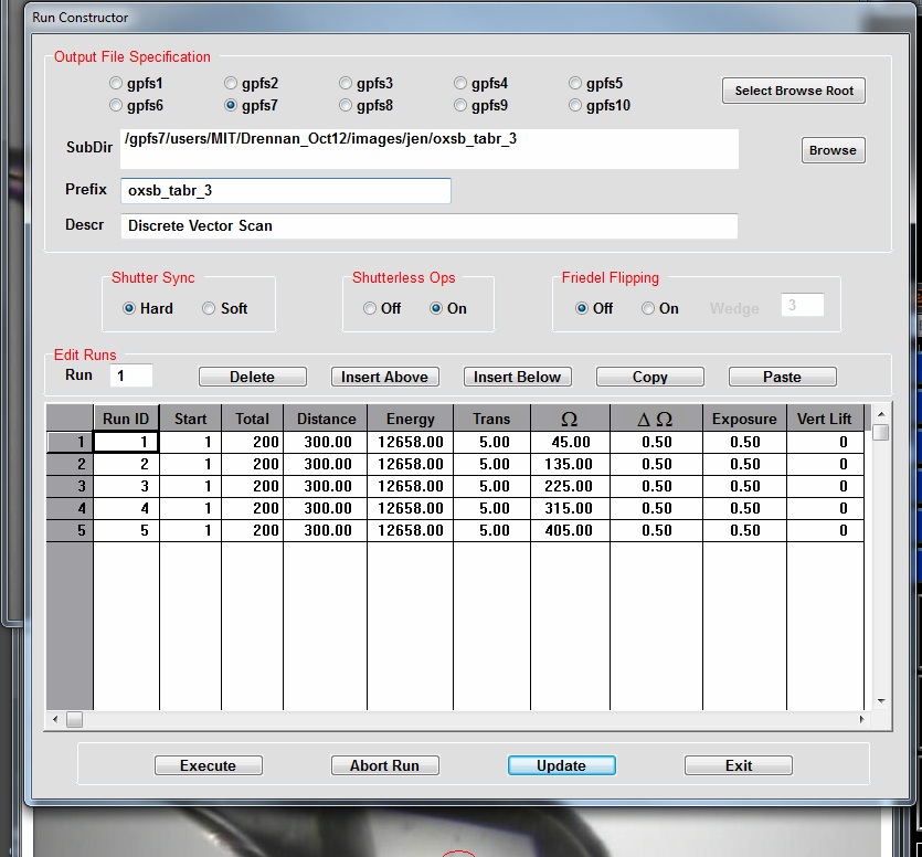
Figure 8. Run constructor dialog.
Here you choose all parameters for standart data collection: Every field can be manually edited, as necessary. First, you need to define the root directory for your data collection (unless that was not done earlier) - by clicking on "Select Browse Root". It should be the images sub-directory below the directory assigned to your group. Next click on "Browse" button and select, or create a new directory, for current project. Next type the file prefix in the corresponding field. Select binning mode (1x1 or 2x2), and "Friedel Flipping" and corresponding wedge size. "Shutterless Ops" should be ON for fast and precise PILATUS-6M detector. Type in Run ID, Number of frames, Detector distance, Initial (omega)phi angle, Oscillarion range, Exposure time, and Transmission. Repeat for another run , if necessary (figure above shows an example of five runs of 100 degrees each with 10 degrees overlap between runs). Once all values are checked, press "Update" and "Execute". EXECUTE leads to collection of defined run. EXI close the dialog window and return operations to DATA COLLECTION tab window.
ADSC data collection can be aborted by pressing "ABORT RUN" button on dialog menu or “ABORT RUN” button in the middle right area of “DATA COLLECTION” tab – see Figure 7. This operation is slow and several images may be collected, before the run is completely aborted; please wait and do not press any other buttons.

More complicated scenarios are defined when pressing
"DATA MODE" button - see menu at right -->
2B. STATIC ALIGNMENT – described above
2C. SATC PREDICTION -under development
2D. BEST STRATEGY - under development.
2E. DISCRETE VECTOR SCAN- discrete data collection all over the predefined vector along your crystal (vector is defined by recording two (or more ) points on Centering tab window (see above). A new setup window will appear where you choose the aperture size, zoom view and omega angle for visualization. Next select rastering parameters: Inset - the shift to the right from the leftmost raster vector point for start of data collection. Offset (usually more than aperture size) is the shift along the raster vector for next data set collection. Cycles - number of data sets to be collected. Phi Offset - is the shift of phi/omega angle between different data collection points. Note: for continuous data collection PhiOffset should be equal number of "Frames" number times "Del Omega".
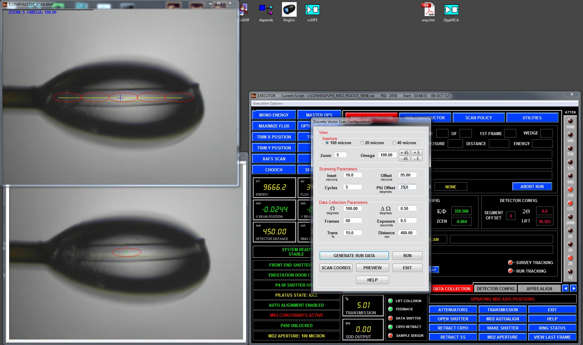
Pressing "GENERATE RUN DATA" will open a graphics window in the top
left corner, where you may
monitor relative positions of every run along the raster vector. Change
Omega values to check the alignment at different orientations. Press
RUN and a “Run Constructor” dialog will appear (Fig. 8).
In the "Run Constructor" dialog window you should setup subdirectory for data collection and file prefix (see above), check the correctness of all runs. If there is any mistake, Click "Exit" and go back to "DATA MODE" and make all changes in the "DISCRETE VECTOR SCAN" dialog. If all runs are correct and all values are checked, press "Update" and "Execute". EXECUTE leads to collection of several defined runs along your crystal. EXIT closes the dialog window and return operations to DATA COLLECTION tab window.
Note. The Discrete Vector Scan mode is best used for very fast and precise shutterless mode of data collection using for Pilatus-6M detector – approximately 120 images are collected in one minute. The shutter is opened and closed only once during data collection.
The CONTINUOUS VECTOR SCAN (described next) provides better protocol to decrease radiation damage, as the crystal is rotated and shifted after every collected image.
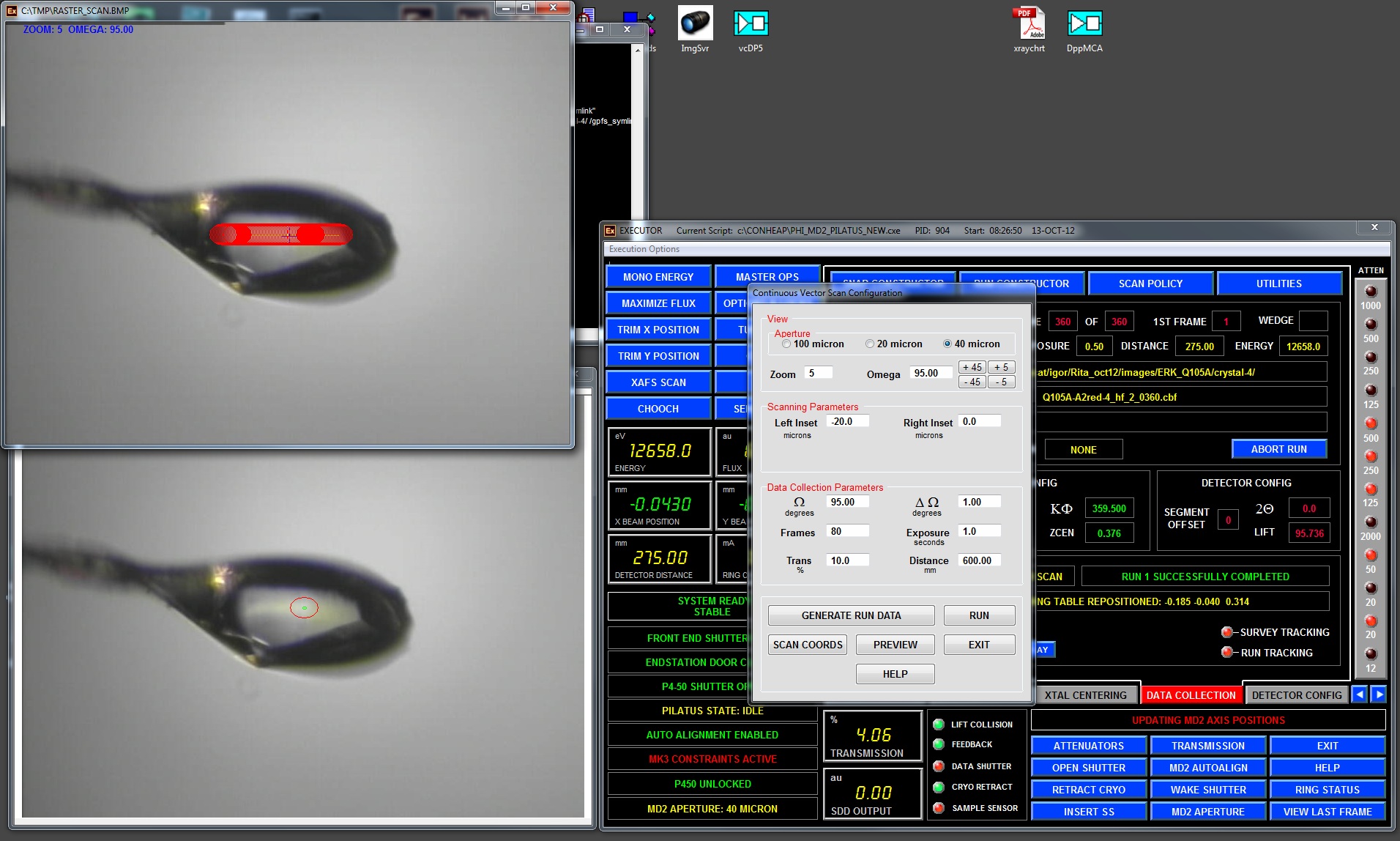
2F. CONTINUOUS VECTOR SCAN –(sometimes called helical
scan) – more advanced mode as compared with "DISCRETE VECTOR
SCAN" - continuous data collection all over the predefined
raster vector. In this mode the crystal is translated/rotated after
EVERY image collected to better spread the radiation decay. This mode
is nearly ten times slower as compared to shutterless "DISCRETE VECTOR
SCAN" mode.
LeftInset and RightInset are offsets from predefined raster vector
ends (not zeros - if you want to collect data on a shorted portion of
the crystal). They may be negative if you want to extend data
collection beyond predefined vector. Omega defines the initial view of
the crystal, there are +/-5 and +/-45 degrees rotations buttons.
Next setup data collection parameters based on the calculated strategy by RAPD (initial omega/phi angle, oscillation range, number of frames, exposure time, transmission and detector distance).
Pressing "GENERATE RUN DATA" will open a graphics window on the left, where you may monitor relative positions of every image point along the raster vector, with all data collection point simulated in red.
Pressing “RUN” will open ADSC data collection dialog which show only one run and it should not be edited (except run number and directory name). Just press "Update" and "Execute" for data collection.
2G ALIGNMENT BY DIFFRACTION - is used to find your crystal in an opaque/non-clear loop: the loop is rastered by a very weak beam and the software analyzes all collected images to find one with the better and stronger diffraction. In the following dialog window you select the necessary parameters:
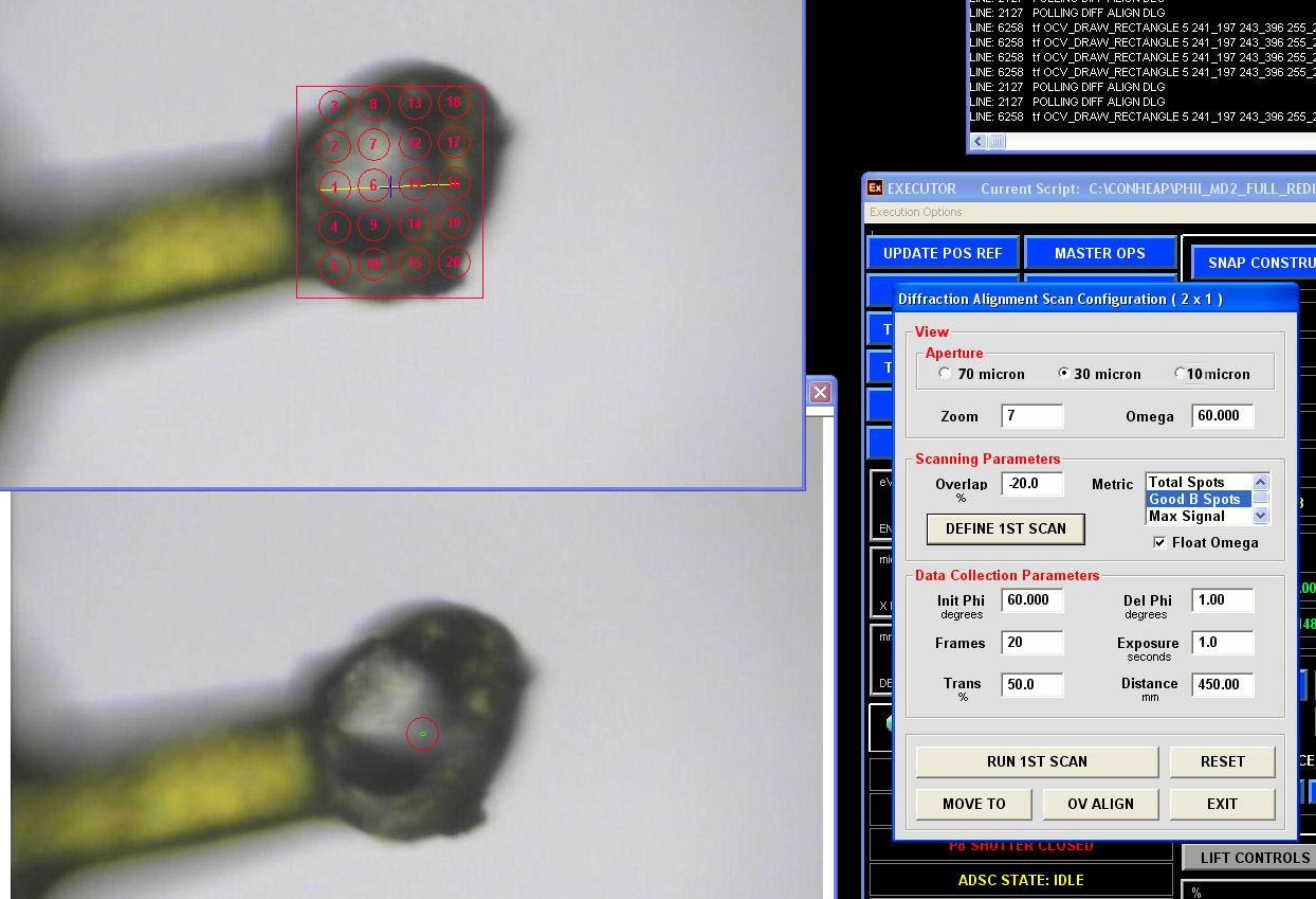
It is recommended to use 70 micron aperture for big loop and use Omega value corresponding to plane of the loop. The "Metric" parameters are used by DISTIL to recognize best diffraction: "Good B Spots" is the best choice for now. "Overlap" defines the overlap between different search points: use a negative number for a sparse search.
Press "DEFINE 1ST SCAN" and a new window will appear in the top left side, use the left mouse to define a rectangular search box. The final search area will be automatically defined as a convolution of your search box and image centering server oval covering the loop.
Change transmission value to 1% or less and define the desired detector distance. Exposure and DelPhi should be 1 second and 1 degree. Press "RUN 1ST SCAN"; the system will move the loop through all red circles/ellipses and store the corresponding coordinates. After that on ADSC computer the diffraction images will appear. All images are stored in "/gpfs1/users/necat/phi_dfa_1/in" directory and will be deleted after exiting the ADSC tab. The message will appear when the run is complete.
A table with processed results will appear, on which it is possible to select different points and check again the corresponding diffraction (can be also done by making selection in lower left graphics window). Once the region of the best/strongest diffraction is found, pressing “MOVE TO” will center that portion of the loop for subsequent data collection. Or if it is necessary, you may proceed and scan the orthogonal orientation using the “OCCLUDED VIEW”. If successful, the loop will be centered on the best "diffracting crystal" position. Click EXIT to close the Diffraction Alignment dialog. Proceed now to the data collection by pressing RUN CONSTRUCTOR
2H. RASTER SNAP
In the dialog window choose the aperture size, zoom and omega angle for specific crystal orientation. Next select rastering parameters: LeftInset and RightInset are offsets from predefined raster vector ends (not zeros - if you want to collect data on a shorted portion of the crystal). Frames - number of snapshots to be collected along the crystal. Select starting angle, oscillation range, exposure, transmission and detector distance.
Pressing "GENERATE RUN DATA" will open a data collection dialog and in a graphics window in the top left corner you may monitor relative positions of every run along the raster vector at the orientation defined by OMEGA value. You may change it for different view, and press again "GENERATE RUN DATA"; once satisfied, click EXECUTE and on ADSC computer you may monitor the incoming images. After the completion of the "raster snap" run another window with simple results will pop-up:
You may analyze (and plot) the results table to find the best portion of the crystal. Or you may select any position of the crystal and press "move to" to center that portion of the crystal.
2I. OCCLUDED VIEW Alignment - With very thin crystals, it is often difficult to visually discern the location of the crystal when in the plane of the loop. First, you need to center at any point in the loop. Second, choose the view corresponding to the plane of the loop (Occluded View), and define a box for scanning. The software calculates a series of points for scanning perpendicular to the plane of view based on user-entered criteria, and then takes snapshots at each point.
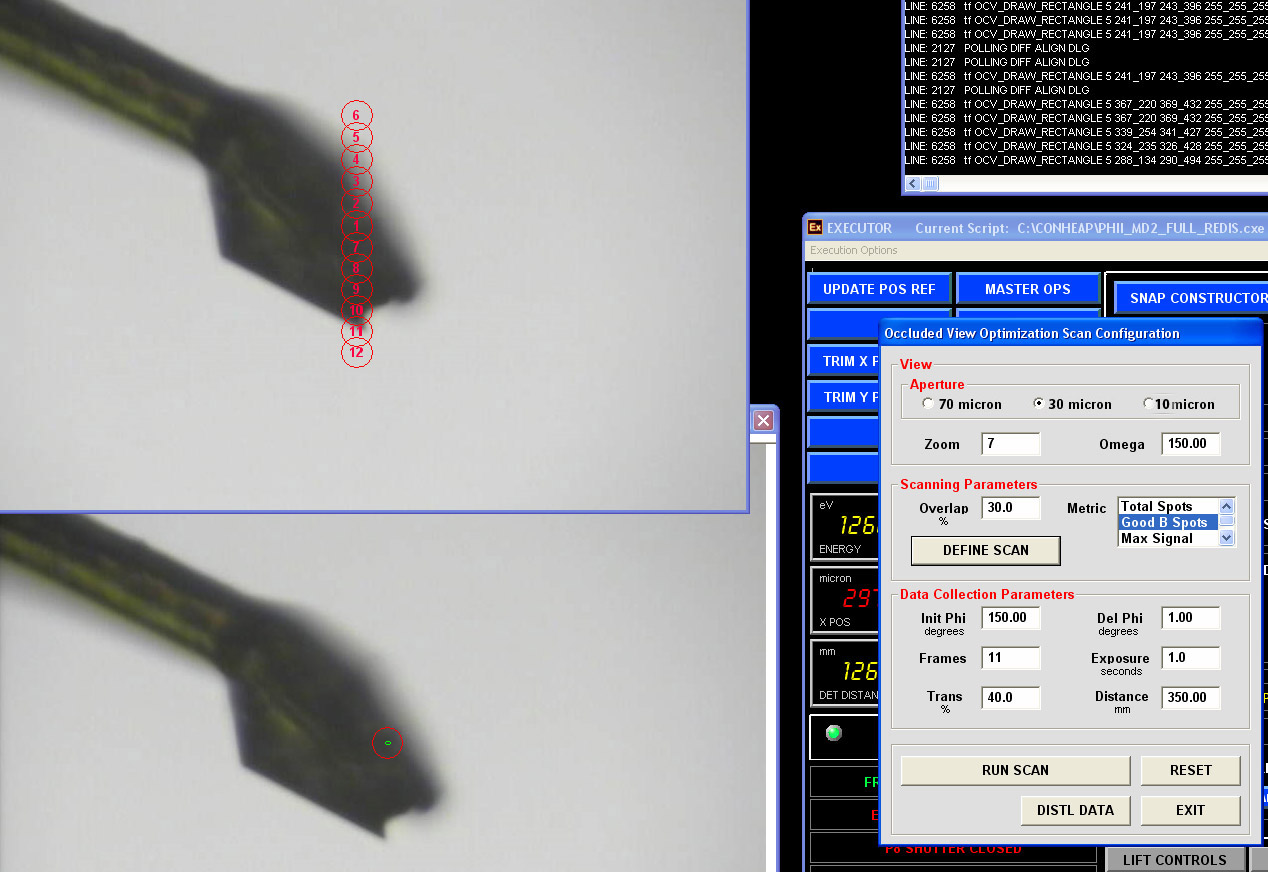
A summary of the diffraction metrics are displayed and you can select a point corresponding to diffraction maxima which causes the MD2 x,y,z centering stages step to the selected scan point coordinates. This point can then be entered into the vector database for use in other vector-based scanning methods.
ADSC data collection
can be aborted by pressing "ABORT RUN"
button in the top right corner.