All in One Window Beamline Controls (under development)
Under active development is a new CONSOLE script, which permits
most of
the
user's operations within a single window using tabular format. The user should paid a lot of attention to updated features and detailed instruction given by your support personnel.
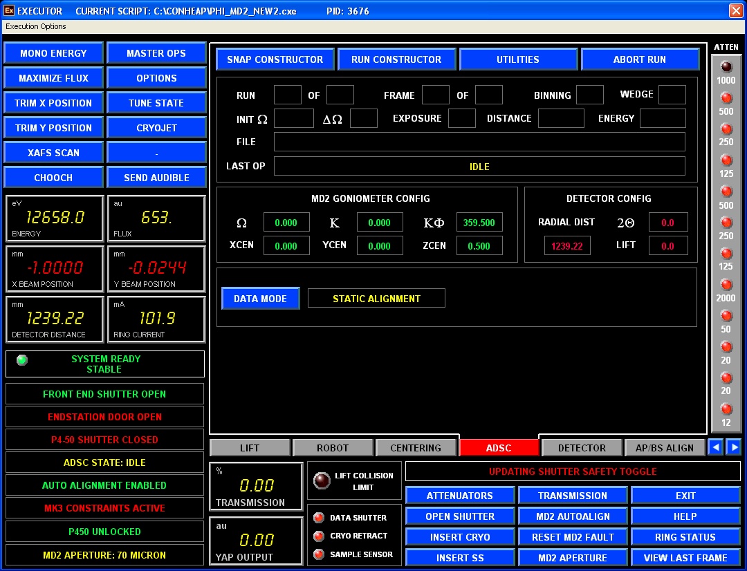
Now on the AUXILIARY computer, when you are starting PHI_MD2_NEW2.CXL script (how to start the script see this), you will see different tabs:LIFT, ROBOT, CENTERING, ADSC, DETECTOR, AP/BS ALIGN, and some others (for beamline personnel use only)
LIFT: is used to manually move MD2 table in vertical and horizontal direction relative to the beam (as described here). These days, this screen is used mostly by the beamline personnel, as all users prefer to use "AUTOALIGH".
ROBOT tab is described in more details in Robot Operations section.
CENTERING is the extension of the centering mode of MD2 software for optional mini-kappa goniometer.

There are several embedded operations in this window (from left top corner clockwise):
1. Robot puck ID number and the button to mount next crystal "CHANGE"; when "BUSY' light is on - the robot is busy doing something, wait before clicking.
2. Section to control camera zoom, lighting of the crystal, and ability to acquire or view your crystal picture. StartServer button should be used only if the the separate visual windows is not started automatically.
3. Controls to manually adjust Kappa/Phi/Omega for mini-kappa; if using single-axis goniometer-only omega should be used; predefined crystal rotations to check the alignment.
4. The function to acquire STAC strategy parameters from RAPD for better crystal alignment (long axis close to omega rotation axis) and align the center of the crystal at new kappa/phi. Make sure you are using the correct values and the most recent ones.
5. Three button to change MD2 mode: Center(default), Data collection and Sample Transfer
6. 3-CLICK alignment tools, including alignment for crystal rastering: First, CLEAR the database, second do 3-CLICK at the beginning of the raster vector, press RECORD; third, repeat 3-CLICK centering at the end of the rastering vector, and press again RECORD, it should be number 2 in the left box. DISPLAY will show consequently the beginning and the end of the raster vector and REPLAY will repeat two alignment processes. More than two points may be created for complex cases.
7. Autocentering function: press AUTOCENTER, and a new graphics window will open on the right side and quick centering either on the loop or on the well defined object will be done. Don't expect the magic of finding "invisible" or very small crystal. REFINE CENTER will repeat the autocentering at higher zoom. Press START IMG SRVR if the new graphics window at right is not started automatically. When "BUSY' light is on - wait before next clicking.
8.Buttons for manual movements of the crystal: vertical, horizontal and along the beam (out-focus plane). 1, 5 or 10 microns increments.
9. Button HOME AXES will move all value of the goniometer to the default/zero values; should not be used with mounted crystal: it may move it out of the cold stream.
ADSC tab is used to control ADSC snapshot/data collection parameters.
1. SNAP CONSTRUCTOR opens the following dialog window:
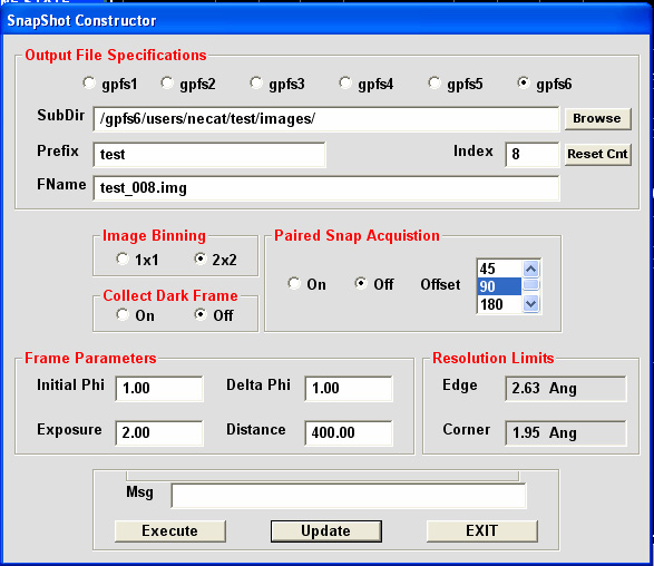
Here you choose all parameters for snapshots (most details are described here ). Paired snap Acquisition is used for poorly diffracted crystal; two images separated by chosen offset value are collected, and LABELIT/RAPD will autoindex them together with much higher success. Resolution Limits are updated once detector distance is defined and UPDATE is pressed. EXECUTE leads to collection of defined snapshot(s). EXIT close the dialog window and return operations to ADSC tab window.
Note: It's VERY important to click "Update" on this window and similar ones for data collection, otherwise previously collected image(s) will be overwritten.
2. RUN CONSTRUCTOR - the following dialogs opens, depending on what is selected when DATA MODE is pressed:
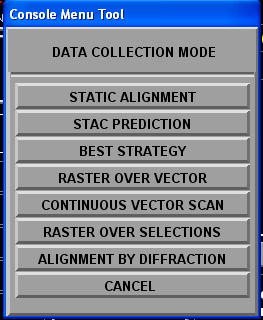
2A. STATIC ALIGNMENT is for usual data collection; it is much like standard ADSC software RUNs setup:
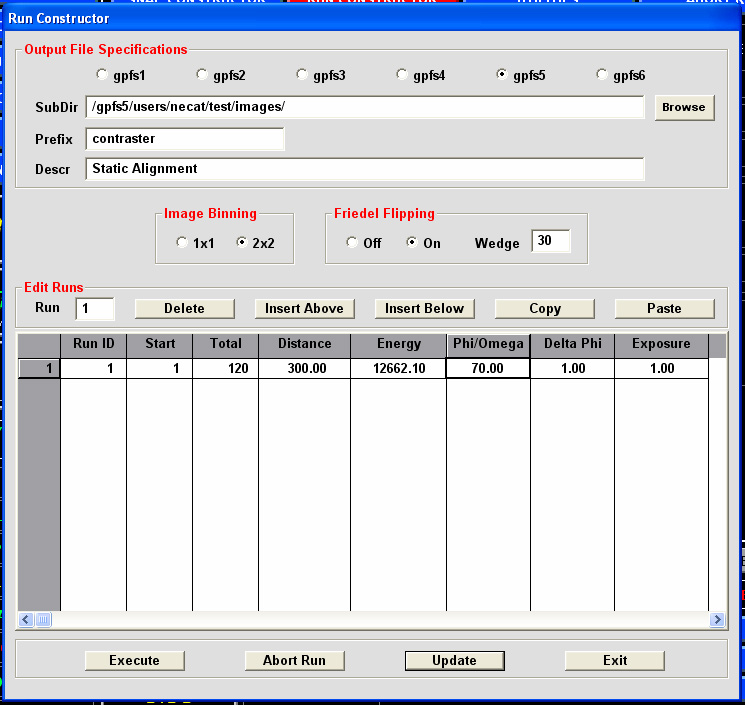
Every field can be manually edited, as necessary. Once all values are checked, press "Update" and "Execute"
2B. STAC PREDICTION - under development for now
2C. BEST STRATEGY - under development.
2D. RASTER OVER VECTOR - For Raster Over Vector (vector is defined by recording two (or more ) points on Centering tab window (see above)
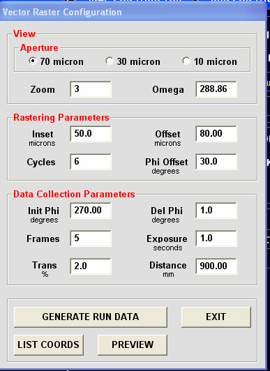
Choose the aperture size, next select rastering parameters: Inset - the shift to the right from the leftmost raster vector point for start of data collection. Offset (usually more than aperture size) is the shift along the raster vector for next data set collection. Cycles - number of data sets to be collected. Phi Offset - is the shift of phi/omega angle between different data collection points. Note: for continuous data collection PhiOffset should be equal "Frames" times "Del Phi".
Pressing "GENERATE RUN DATA" will open a data collection dialog and in a graphics window on the left you may monitor relative positions of every run along the raster vector:
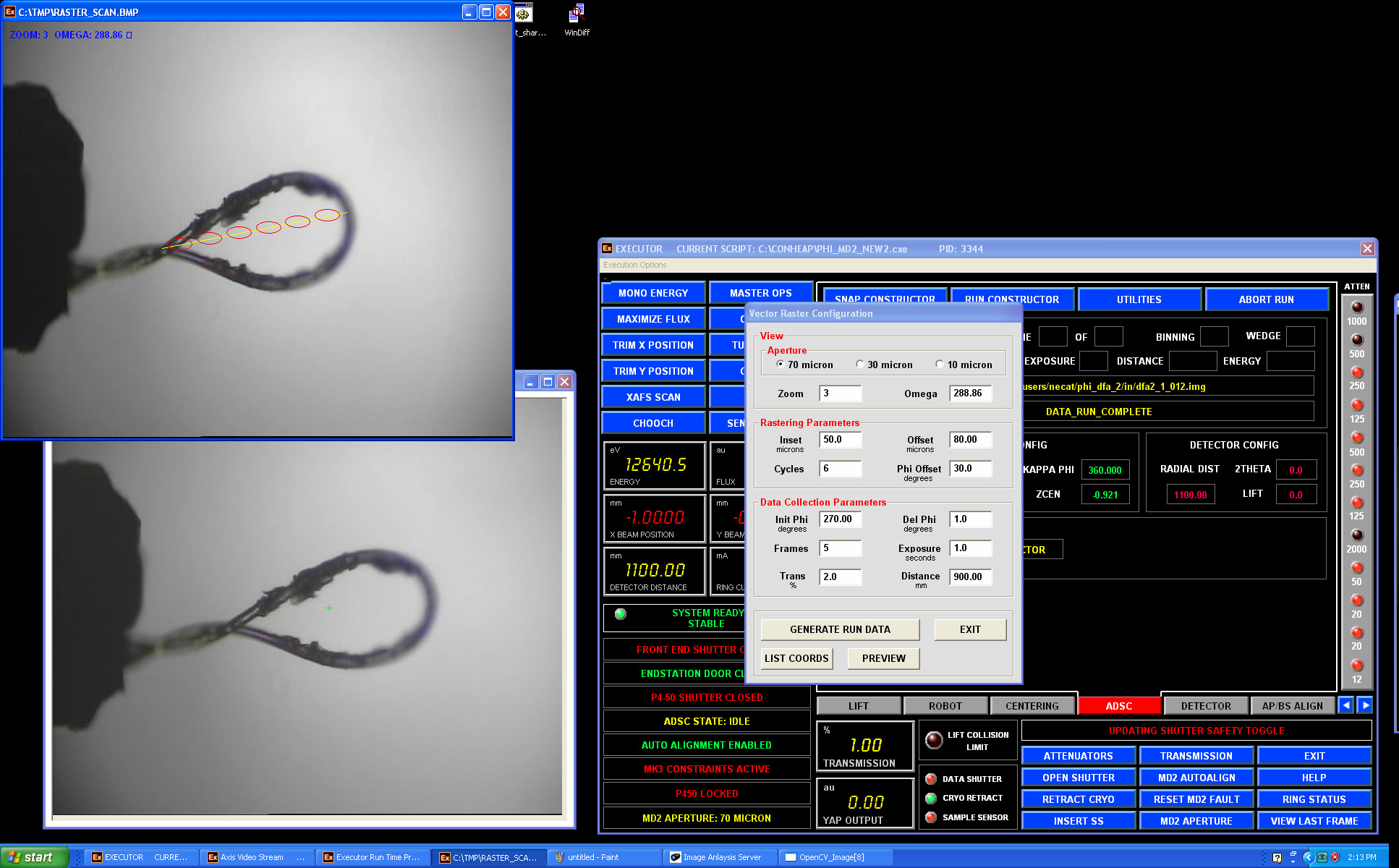
After pressing "Generate Run Data" the final configuration window appears:

It's mostly informational , but all fields may be edited before clicking "Update"/"Execute" for data collection.
2E. CONTINUOUS VECTOR SCAN - continuous data collection all over the predefined raster vector. In this mode the crystal is translated/rotated after EVERY image collected to better spread the radiation decay. This mode is nearly THREE time slower as compared to 2D RASTER OVER VECTOR mode.
in the following dialog window you select the necessary parameters:
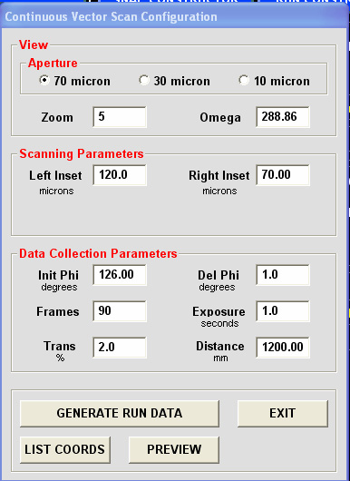
LeftInset and RightInset are offsets from predefined raster vector ends (not zeros - if you want to collect data on a shorted portion of the crystal).
Pressing "GENERATE RUN DATA" will open a data collection dialog and in a graphics window on the left you may monitor relative positions of every image point along the raster vector, with all data collection point simulated in red :
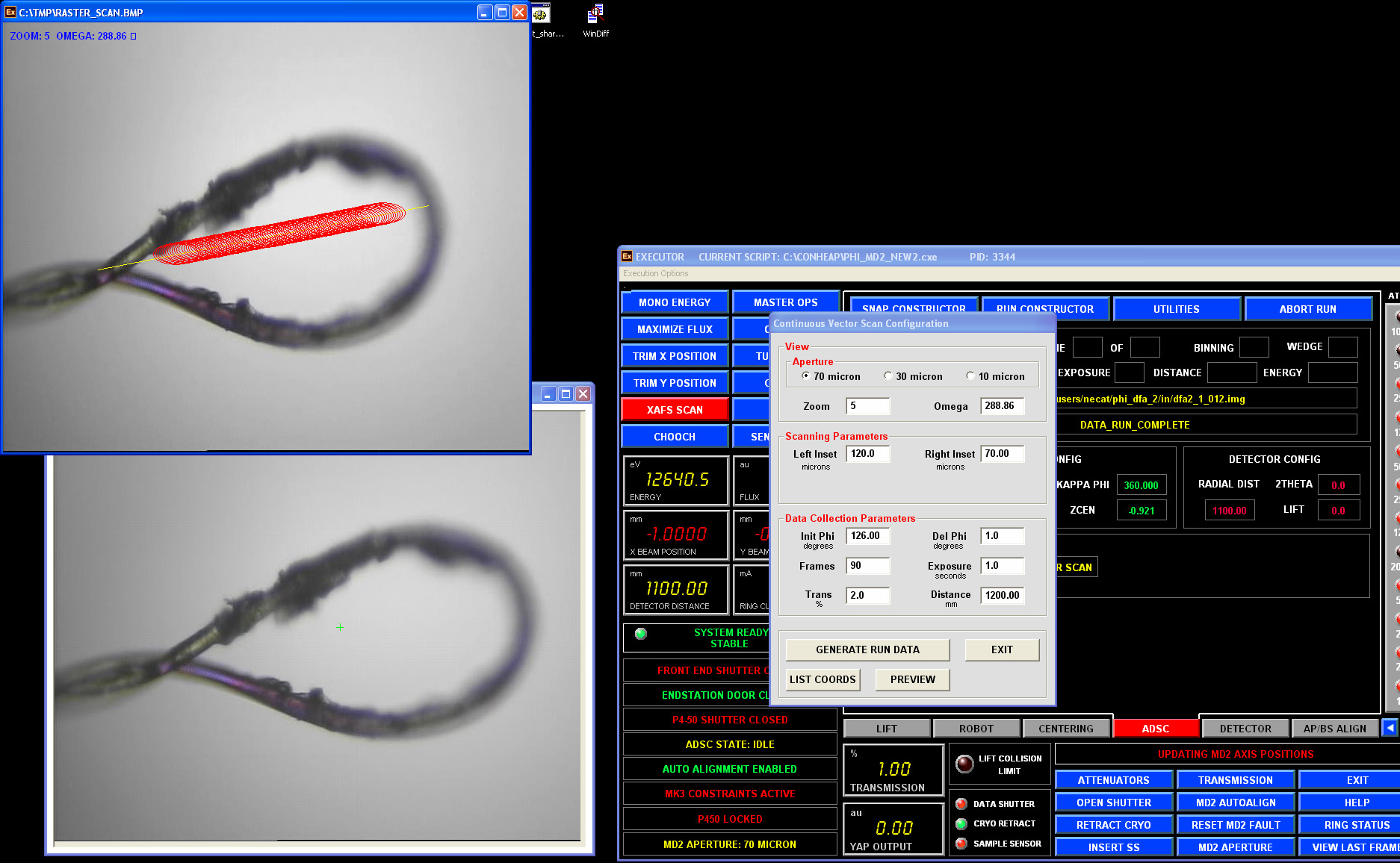
ADSC data collection dialog will show only one run and it should not be edited. Just press "Execute" for data collection.
2F ALIGNMENT BY DIFFRACTION - is used to find your crystal in an opaque/non-clear loop: the loop is rastered by a very weak beam, in the following dialog window you select the necessary parameters:
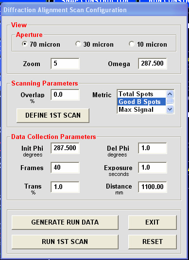
It is recommended to use 70 micron aperture and not to change Omega value (it defines the internal plane of the goniometer).
The "Metric" parameters are used by DISTIL to recognize best diffraction: "Good B Spots" is the best choice for now.
"Overlap" defines the overlap between different search points: use a negative number for a sparse search.
Press "DEFINE 1ST SCAN" and a new window will appear in the top left side, use the left mouse to define a rectangular search box.
The final search area will be automatically defined as a convolution of your search box and image centering server oval covering the loop.
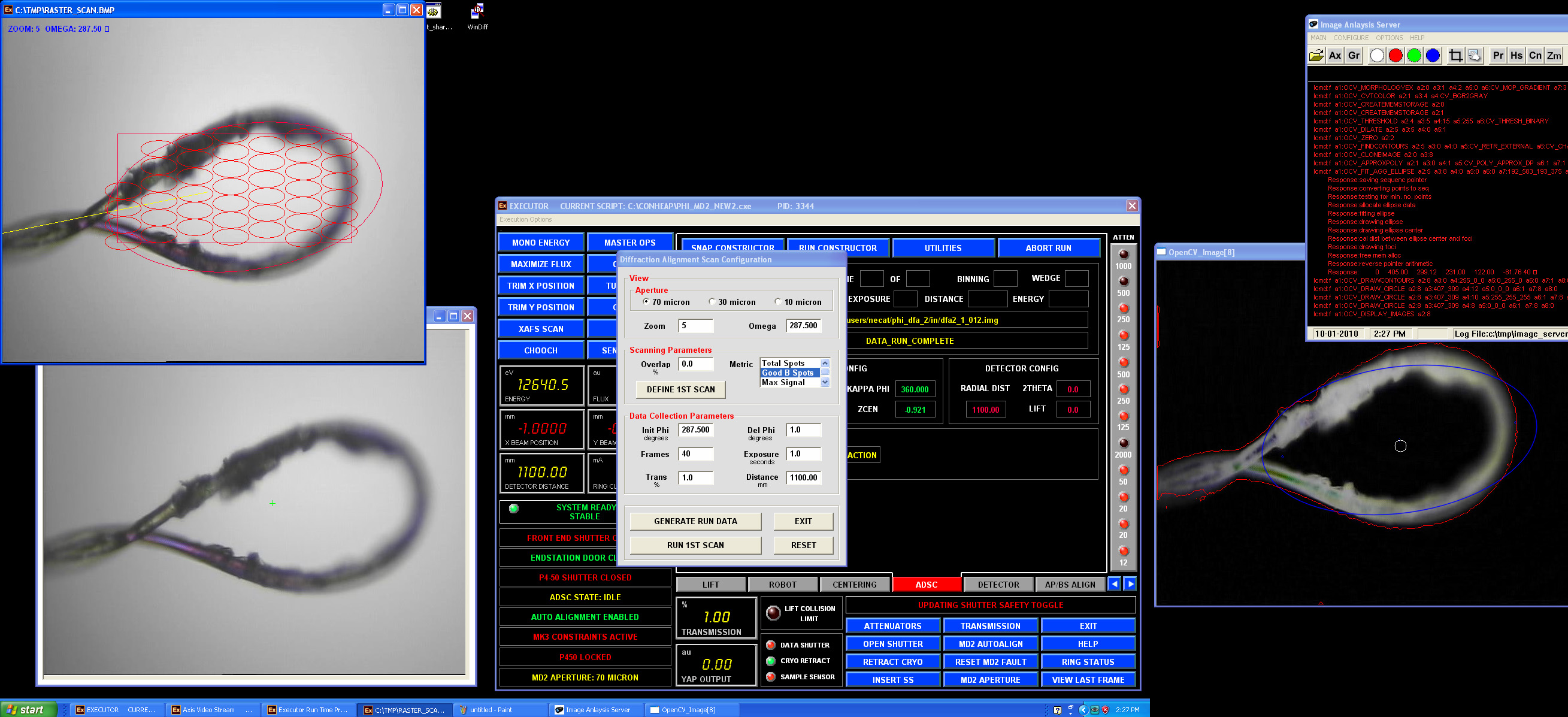
Change transmission value to 1% or less and define the desired detector distance. Press "GENERATE RUN DATA"; the system will move the loop through all red circles/ellipses and store the corresponding coordinates. After finishing press “RUN 1ST SCAN”; now on ADSC computer the diffraction images will appear. All images are stored in "/gpfs1/users/necat/phi_dfa_1/" directory and will be deleted after exiting the ADSC tab. The message will appear when the run is complete.
The search points with the "diffracting crystal" inside will be drawn in bright red. Now you need to repeat the same procedure in the orthogonal orientation: Press “DEFINE 2nd SCAN” and repeat all steps above. If successful, the loop will be centered on the best "diffracting crystal" position. Click EXIT to close the Diffraction Alignment dialog. Proceed now to the data collection by pressing DATA MODE ->STATIC ALIGNMENT.
ADSC data collection can be aborted by pressing "ABORT RUN" button in the top right corner.